
|
|
|
home - 1UP Game Series - aaSNES1 - JetPak DX |
aaSNES1 Acer Aspire One A150 / Super Nintendo Entertainment System (UK) remix. Take one of the greatest games consoles ever made, the Super Nintendo Entertainment System. fig.(1) then gut it to place a fully working PC inside of it. I decided on using an 8.9inch Acer Aspire One (AA1) fig.(2) as a donor, as it's one of the smallest Atom 1.6Ghz computers out there. Taking the thing apart I found the mainboard to be a very good size to fit inside the SNES, but taking the SNES apart, there was much plastic to be dremelled out, to make room for everything. Also a huge hole had to be cut out at the back so the mainboard would stick out far enough to give access to the power, VGA, ethernet and USB port. To mount the mainboard, I struck upon the idea to use Lego bricks, this allowed me to build supports in different shapes and sizes with much ease. We mounted the daughterboard up at the front of the SNES as this allowed the power LED of the AA1 to line up with the one on the SNES. I wanted to have the power switch turn on the mainboard, but as the original switch was a toggle switch, so it had to be converted to spring back. My genius of a partner was able to dismantle the original SNES switch and remove the toggle latching mechanism, so it freely moved between on and off. Then he wired the switch to contact points on the mainboard where the original AA1 power button was. Finally a carefully placed spring, made sure the switch would spring back after being flicked to the on position. I also wanted the SNES eject button, to trigger the eject mechanism on the DVDRW drive. Speaking about the DVDRW drive, I decided on a slot loading drive, this way I could hide it within a games cartridge and still access it. Unfortunately the drive was just a fraction too big to fit in a UK sized cartridge. (Should have used an american SNES). No matter. I cut away at the front and back halves the best I could so they would cover the DVDRW drive. One issue we ran into was how to power the DVD drive and get the USB data from it, as there is only 3 USB ports on the AA1. With a bit of research we found we could tap into a USB data signal on the internal Mini PCI slot, and grab 5volts off a transistor, a further 5volt feed was taken of where the Synaptics touchpad would have connected. With some more deft soldering skills from my collegue, we had data feed and enough power for the DVDRW drive. The next step we took was to extend the audio feeds from the daughterboard to the back of the SNES, where I would drill two holes to attach 3.5mm stereo sockets. Take a look at fig.(3) to see how far we had gotten after 3 days of work. As you can see the DVDRW drive sits quite high, so the SNES cartridge isn't all the way down in the slot. We tried our best to reduce the height, by modifying the DVDRW USB controller board. But disaster struck when we relocated the timing crystal, the controller board stopped working. So until new parts arrived we had to use my non slot USB DVDRW drive to test it with. One of the other parts we were waiting on, was an SATA (data+power) extension cable. It seemed I could only order one of these from Hong Kong. But with the extension cable we were able to relocate the harddrive from under the mainboard at the front, to up at the back. Using some more Lego we built a platform for the harddrive to sit on. My compadre realised by cutting a small notch in to one of the supports, we could fit the MiniPCI Wireless adapter in. So we took out the antenna cables from the AA1 and attached them to the WiFi card. I was originally going to mount a USB socket in the middle of each joypad port, behind a plastic blanking plate made from a left over SNES cartridge shell. But a friend gave me the great idea to just use the original SNES joypad connectors and put the USB sockets on the ends of those. We tore the connector apart and attached one end of an USB extension cable to it. Then with a quick flick of the wrist or two, comrade soldered the SNES joypad ports to the USB points on the daughterboard. In fig.(4) you can see the harddrive sitting on the mount with the extension cable, the WiFi card fitted with antenna and the USB to joypad conversion. My associate thought why don't we include the webcam and mic as well, genius idea I said, so drill a small hole in the front of the Super Mario World cartridge for the webcam lens, then mount the microphone right at the front of the SNES in the centre of the front vent. Putting the two halves of the SNES back together you can see, in fig.(5) the webcam works great, also see where the discs go, although the drive isn't currently working due to the damaged controller board. He then has the further idea for a bit of bling we could make the SNES logo on the top right of the casing light up. And light up it shall, as he connects 4 LEDs to where the old harddrive activity LED was on the mainboard. I drill 4 holes to mount the LEDs in, right behind the SNES logo. Now as the harddrive is accessed the SNES logo lights up. Beautifully shown in fig.(6) Around the back of the SNES there was quite a big hole from where the original backing plate was, since the had been removed to make room for the mainboard, we had to use something to fill it in with. Bring in the trusty Lego, the grey bits of Lego go quite well with the colour of the SNES casing I think. You can see the power socket, VGA, ethernet and back USB poking out the back of the SNES in fig.(7) with the Lego "backing plate". You can see in fig.(8) the rewired SNES controller plugs to USB ports. It was literally hacking of the ends of two USB extension cables, then opening up the SNES controller ports, taking out the pins, removing the old wiring, then soldering the USB cable to the the pins. These USB breakout cables plug into the SNES joypad ports, which are have their corresponding pins wired onto the USB ports that were on the AA1's daughterboard. I ordered some cheap as chips USB SNES-shaped joypads, when they arrived I couldn't believe how cheap the plastics used were. But that was okay, I was interested in the insides of the joypad. Taking it apart I pulled out the incredibly simple pcb and transplanted it into the casing of an original SNES joypad. It didn't go 100% smoothly, as although the moulds for the plastics were very similar they weren't exactly the same, so with a bit of cutting and drilling here and there, oh, and replacing the shoulder buttons contacts for the original SNES ones, we got a PC USB SNES joypad. See fig.(9) Next came the saga of the audio ports. Now I thought this would be simple, we just run extensions off the headphone and microphone ports on the daughterboard, and attach them to the back of the casing. Oh dear, but then we decided it would be cool to have the speakers built in to the casing, kind of like an iMac I guess. The problem is, when you plug something into the headphone port it disables the speakers. This we worked out is to do with a break switch in the socket. We wanted to replicate this function in the extended audio sockets at the back of the aaSNES1, so ordering 2x 3.5mm stereo audio break switch sockets, we thought we were in business. Oh no, how wrong we were, after spending a good hour trying to work out which solder point related to left/right/ground for the audio, we finally worked out when plugging a jack into the headphone socket of the daughterboard, it actually MADE a circuit which turned the internal speakers off, not as we initially thought a BREAK. With that established, the audio break sockets I ordered were no good, they were doing the exact opposite. We tussled with a few options, just take out the internal speakers completely, wire a seperate physical switch that the user has to toggle to turn the speakers on or off, both we really didn't want to do as it would just compromise the whole experience. Examining the audio break switch sockets we had purchased, we decided if we could add another pin/contact inside the switch, so it would MAKE a circuit, that would solve our problems. As tiny as they were we decided it should be possible, at first I wanted to drill a hole in the side of the switch, but we didn't really have a drillbit small enough. My partner came up with the idea, of heating a leg from a LED with the soldering iron and just melting our way into the switch, which is what you can see happening in fig.(10). And with that sorted, we had our insert to make switches, they were soldered in, then attached to the back of the casing. With a handfull of new timing crystals for the DVDRW controller, one was soldered on the board. But unfortunately the DVDRW drive was not being detected. It would appear the whole board was gone. No matter, luckily I purchased a complete new external USB slim CDROM housing. We just swapped out the controller boards, soldered on the the extended usb/power connector, and we had a working DVDRW drive again. Putting the DVDRW drive inside the two halves of the cartridge and then into the cartridge slot, was an extremely tight fit, so tight that it was actually flexing the sides of the drive. This meant when I tried to insert a disc in to it, it just would not fit. Out came the trusty dremel and I widened the slot just enough for it to all fit comfortably. We've taken the old push switch from under the reset button on the SNES and relocated it under the eject button, then wired this to the eject button on the DVDRW rom. Only slight problem at the moment is, that the eject button is so wide it doesn't really sit very well on this small push switch. Maybe we'll make some guide rails for it. I still don't know what I'm gonna do about the sides of the cartridge though, maybe it will come to me later. The thought of adding internal bluetooth was brought up so bluetooth keyboards/mice/etc could be used, and for Mr Solder (DuPPs), this would be no problem, we located another internal USB feed, grabbed an old bluetooth adapter, tore it apart and soldered it in. But it wait it doesn't seem to want to work. It appears this USB adapter is very much old and dead, never mind, while testing to see if was actually working correctly, DuPPs has soldered an actual USB port internally, so adding any new USB devices inside will not be a problem. Just have to pick up a new USB bluetooth adapter and plug it in. The project is now completed, but I've gotten lazy and tired, so don't want to write much more about it. To help with the airflow and cooling we fitted a 25mm fan at the back left of the casing, this was a 5volt fan, which was wired into one of the 5volt feeds on the LCD connector. For the internal lights at the front, we soldered 5 white LED's together in parallel, stuck a resistor in there, and wired it to the other 5volt feed on the LCD connector. I forgot to mention Dupps, took off the power LED from the daughter board, then soldered on a much more brighter green LED which was glued into place right below where it should be on the SNES casing. There is probably a few more things we did to the mod, but I'll let the videos speak for themselves. I'm just excited it's finished. Project completed on the 13th of June 2009. quangDX and DuPPs |
photos fig.(1) 
fig.(2) 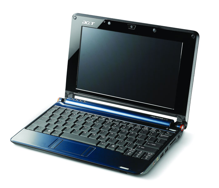
fig.(3) 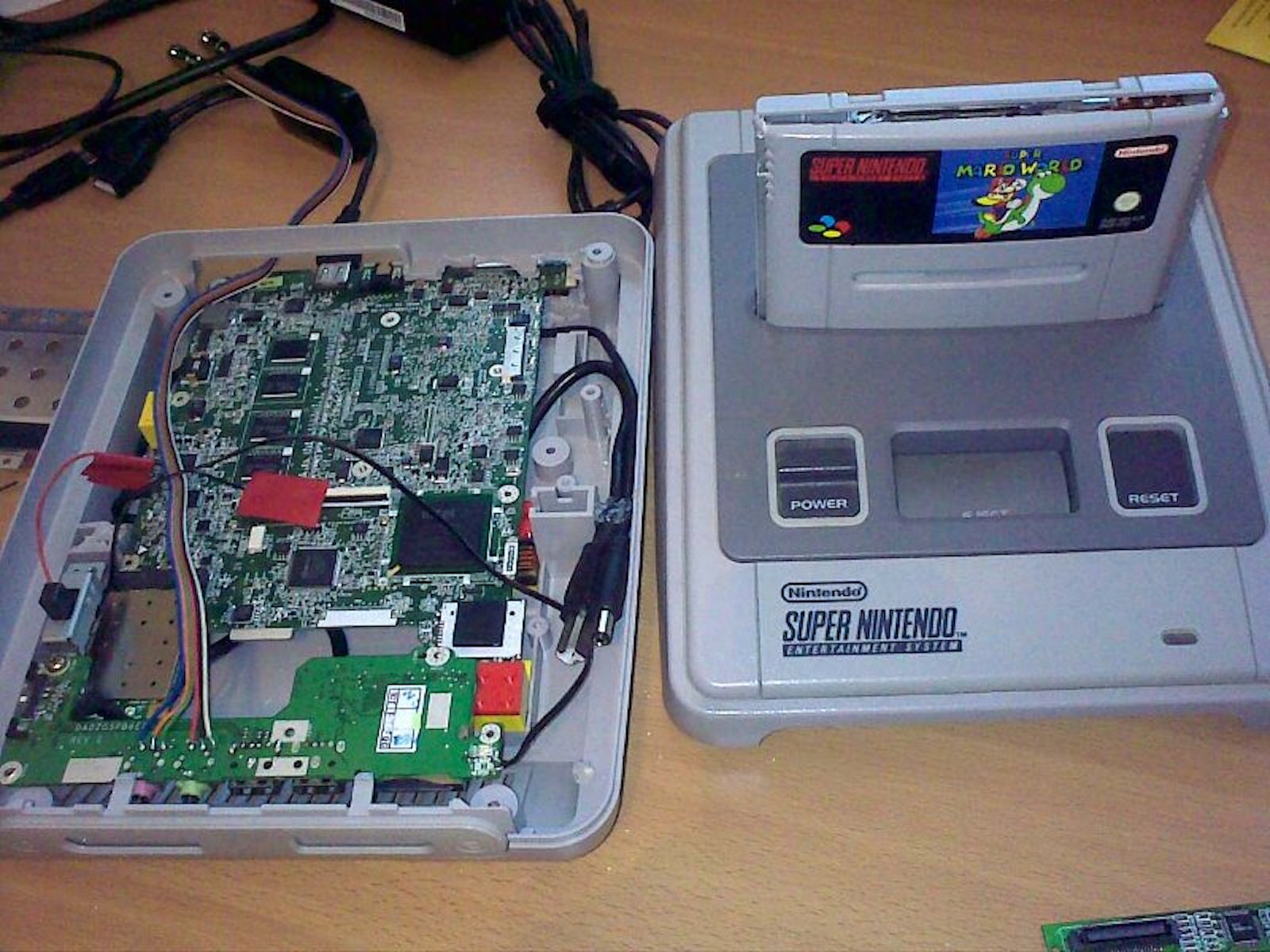 fig.(4) 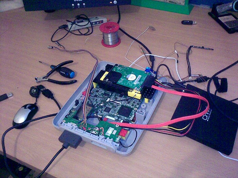 fig.(5) 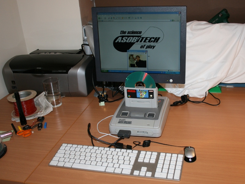 fig.(6) 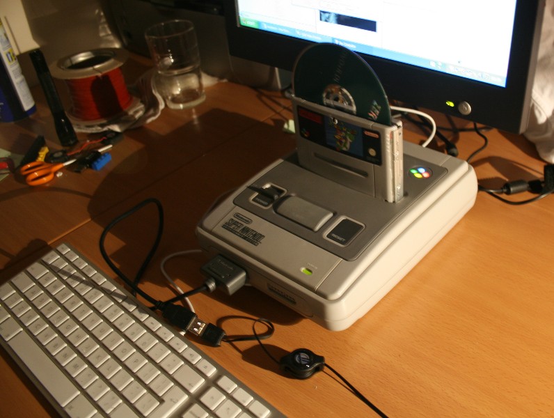 fig.(7)  fig.(8) 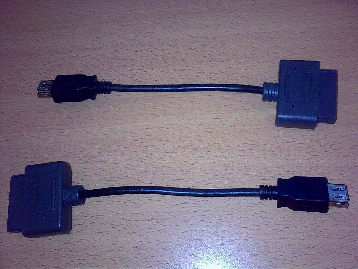 fig.(9)  fig.(10) 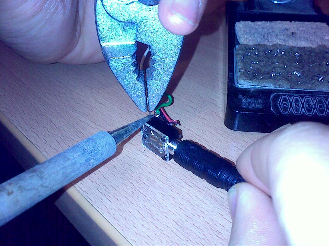 |
2009 asobitech